 By Ing. F.C.T. Gale M.IEEE.
Latest update: 9th February, 2025 21:02 [local, UTC+1].
By Ing. F.C.T. Gale M.IEEE.
Introduction...
A few months ago I was asked to give some help and/or comments for a friend who was having a lot of trouble with interference from 2 installations in his area, and although it was not about amateur radio, at the time I thought that some thoughts on this would be of interest not only to radio amateurs, listeners, r.c. modellers but also (prospective) solar panel owners, installers and even architects and others.
I am writing from my experience and background:- I am a qualified electronics design / development engineer mainly involved in the R.F. part of instruments and systems for use in space, especially for interfaces on scientific satellites.
I have of course studied the problems surrounding current solar panel installations - and before I go into the technical details, I want to mention some of my initial comments first.
Whatever the technical, social or contractual problems are, finding an acceptable solution is going to cost money and take time. In an EMI situation this means that the owner of an installation emitting R.F. interference has to take extra measures to solve such problems - while he or she has actually already heard or read that his installation is (a) safe, (b) economically advantageous, (c) better for the environment and (d) very durable. Oh, also that it falls under the "European Standards" and that it was installed by "our experts". (Of course we, as engineers, radio amateurs and/or listeners will have more technical experience and expertise concerning such interference than the average customer/owner but there are certain aspects of each case that should be considered in my opinion).
So, the average customer has little knowledge of EMC or of the relevant "EU standards" - after all, he or she works at a bank, a car garage, a hairdresser or even as a surgeon at a hospital and is therefore dependent on the people who should have such knowledge. Furthermore, he or she would not know whether the so-called "experts" really have the necessary knowledge, and if so, whether these 'experts' follow the correct methods (e.g. the correct way of wiring). It is worth noting that the "CE" marking of certain equipment and accessories on the market gives no guarantee from casual examination - see the example below.
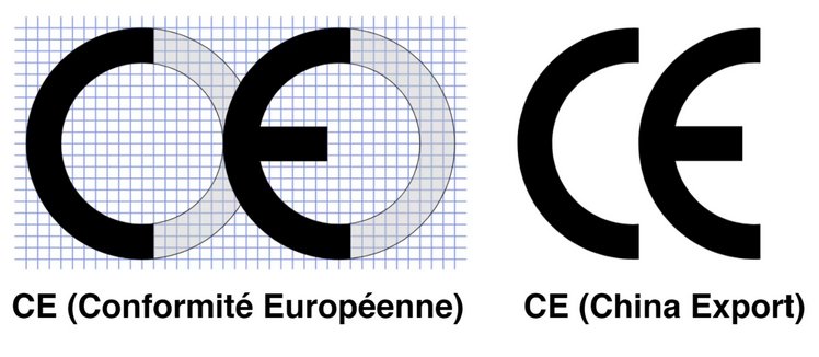
Fig. 0 - Correct, valid and misleading CE marking.
It is clear that the genuine European conformance marking uses equally-spaced and sized character layout, whereas the "Chinese Export" marking does not, and indeed can sometimes be with different spacing.
Non-technical problems..
An average buyer of such an installation is certainly not expecting extra costs and work after the installation is already 'completed'. In my neighbourhood there is a lot of new construction where the houses cost around Eur. 750,000 - 950,000 (with gardens the size of a postage stamp - land is expensive where I reside!) - most of which are sold with a solar-panel installation included.
However, the buyers do not even want to pay Eur. 75 for repairing a window that does not close properly - let alone paying for more expensive solar panel installations or parts thereof.
Therein lies the first problem, because (e.g.) companies and installers might well give 'free' filters to these customers with interference problems, but do not cover the costs of installing the filters - these costs have to be paid by the homeowner through the use of another installation company.
Also, the average homeowner / customer has no idea what kind of inverter and / or 'optimizers' are in the installation, or whether it causes interference like many of "Solar Energy" ones and others, or whether it is properly grounded.
Then comes the second problem and that has to do with the shortage of technically qualified employees who carry out the installation and the fact that few of the installation companies and their personnel have the necessary knowledge of R.F. matters - and if so, whether they follow the correct way of working - because (for example) to use the correct method of wiring between the panels on the roof costs a slightly more while there is a lot of pressure to make the installations cheap and to work as fast as possible. The result is of course that more completely unnecessary interference signals are created.
Inverter efficiency.
A typical inverter would be about 96% efficient - but this can differ, especially if less power is used - for example, a 5kW installation with a load of only 500W we can count on 94% while with a load of 3kW this could be about 97.5%. All in all, with a typical D.C. voltage input to the inverter, at full load we assume a current of about 146A, or roughly 150A for our calculation. It must be realised that, even with an inverter that is 97.5% efficient, on a 5kW installation that is loaded with 3kW (optimal) that about 75W must still be dissipated somewhere else - e.g. as heat or as a transmitted signal(s). At 500W operating load, at least about 30W would still be dissipated.
Such an installation would also have a wiring from the panels on the roof that supplies power to the inverter - and with a simple serial wiring around the panels an ideal loop antenna is realised, although the inverter works well and is efficient itself.
Inverter as a source of interference...
We all know here that an installation inverter works with at least 2 switching 'power supplies' - one for generating approximately 400V DC from the (e.g.) 36V DC (**) of the panels, and one for making 220V sinewave AC from that 400V DC.
A few kilowatts switched at 30KHz - 60KHz by power FETs that have a Vsat of a few volts or less inevitably gives rise to very many harmonic frequencies that have to be filtered out from connections to the inverter or kept within the inverter housing.
In the second switching 'power supply', to make the 'sine' 220V A.C. 'pulse-width' modulation is used - so the FETs are still driven with a square wave with a variable width.
There is no other way to drive the FETs, because if another form of control source is used (e.g. with a lower gate drive voltage) then the FETs would not reach saturation and would therefore spend a much longer proportion of their time partially conductive which would generate a lot of heat (drain-source resistance -> tens of volts Vds times Ids = Watts) which means a lot of wasted energy.
Often, especially in the cheaper models, there are few or no filtering parts where they are really needed.
It is worth noting that there are inverters that give rise to little or no radio interference - in particular the inverters from Growatt and from SMA score well in this respect.
Note - in this article I show single FET’s as the switches, in practice it is quite normal to use a number of FET’s in parallel to manage the high currents involved.
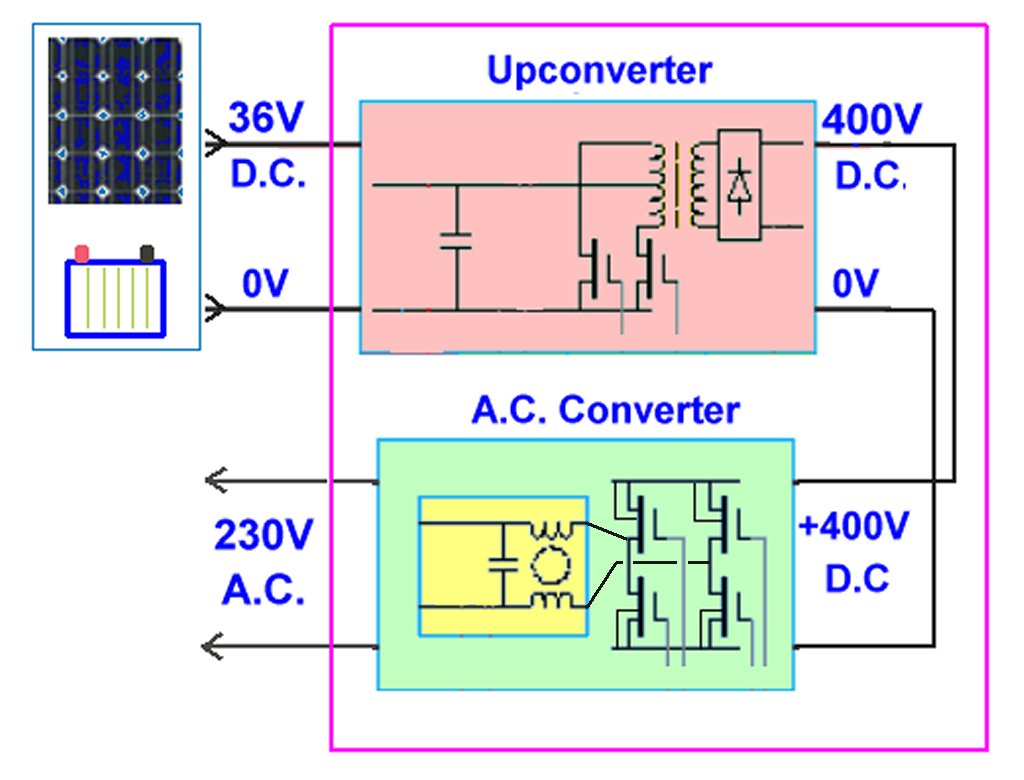
Fig. 1 - Principle of an inverter.
.
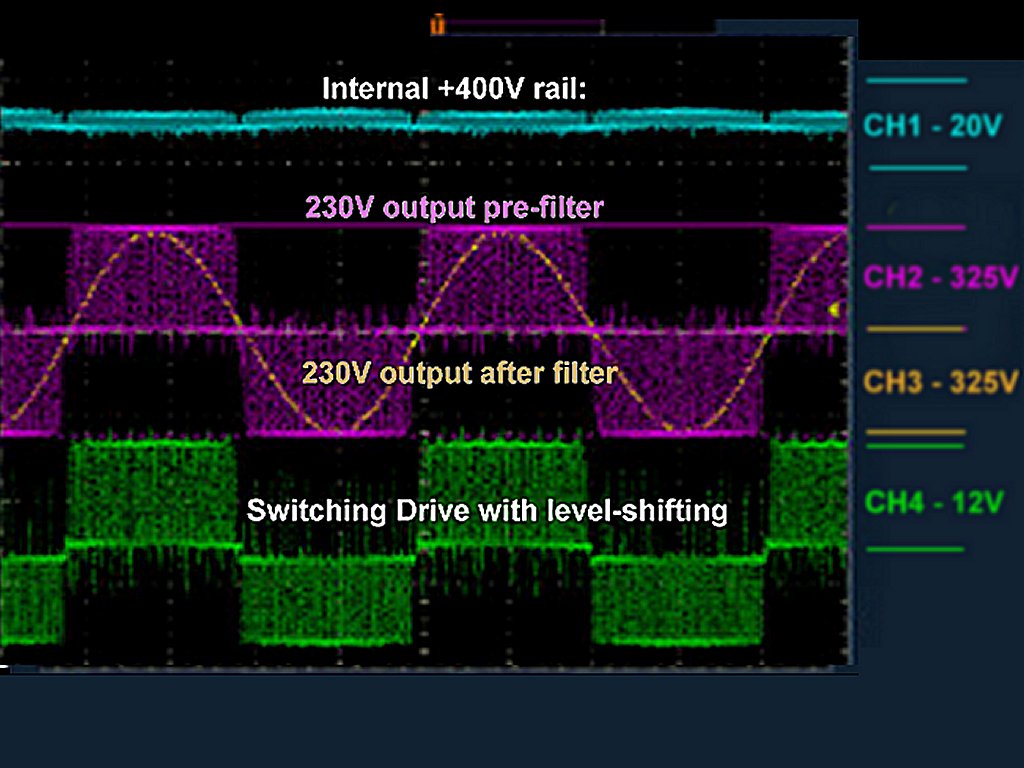
Fig. 2 - Generating A.C. 50 Hz using variable-width pulses.
There are also installations that work with a number of “microinverters" on the roof (smaller inverters that have an input from only a part of the solar panels on the roof) - this has the advantage that less DC current runs through the cables, less high-power components need to be used inside, and the outputs are already A.C. so ready for a combiner at 220V. There are then a number of these micro-inverters on the roof, but each micro-inverter has to perform the same complicated functions as a central inverter, so there is more chance that an error would occur and that can also cause damage to the roof.
(** there are inverters that work with a high DC voltage as input, but I will come to this later in the story).
For the material that I will discuss here, I will take as an example a system with a central inverter.
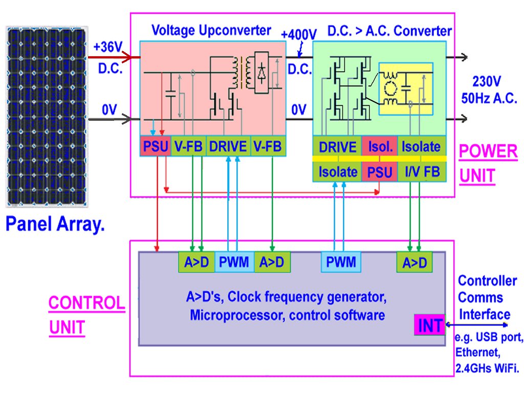
Fig. 3 - A simple example of an inverter.
At the input of the panels a D.C. current flows to the first switching block, and this switching frequency would also go along that D.C. wiring if there is too little filtering within the inverter. The inverter’s eventual A.C. output should actually be 50Hz, but again, if there is too little filtering, there will still be an interference signal present that goes through the wiring in the house.
Normally there is indeed enough filtering for this output such that household appliances are not affected, but the high switching frequency is often not kept within the housing of the inverter (e.g. insufficient 'screening'). The housing of the inverter and connected equipment must be properly earthed to achieve this - even a thick wire that goes to a good earth in the ground is actually worthless if it is about 3 or 4 meters long, it then functions more like an antenna!
Finally - concerning the FETs that are switching - some people would think that if we are talking about 30 to 60Khz then the harmonics would be very weak in the ranges above a few MHz, but nothing could be further from the truth. With a T(on) of 170nS and a T(off) of 270nS we are talking about 5.882 MHz and 3.703MHz signals and their harmonics!
These harmonic signals would also be ‘modulated’ by the 30 - 60KHz control frequency - so one would expect that (e.g. in the 80-m band) there would be an interfering signal every 30 - 60KHz. Worse still, because the control signal to the FETs is pulse-width modulated this interference signal would be wide which is not easy to suppress using a notch filter in the receiver!
For clarification I have included as examples block diagrams of a fictitious inverter and the datasheet page of a fictional FET that might be used in an inverter plus an example of the waveforms within such an inverter.
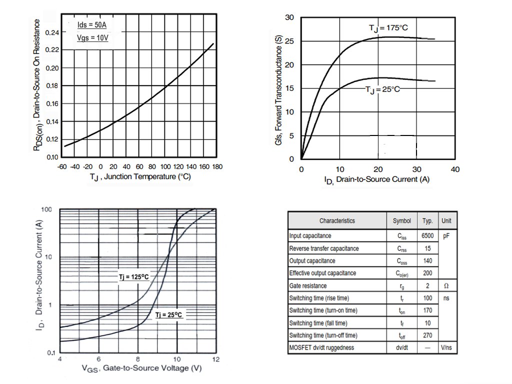
Fig. 4 - Important figures of a switching FET.
Attenuating interference signals.....
Since the inverters in a solar panel installation work with switching 'power supplies’ - and that the first takes care of generating about 400V D.C. from the 36V D.C. of the panels (or ‘house battery’), one of the measures against the interfering switching frequency that we can take is to place ferrite rings or ferrite clamps on the cables that carry the incoming D.C. and on the wiring that outputs the A.C. 220V. Ferrites and ferrite clamps are relatively cheap and are widely used in various electronic devices, including computers, mobile phones and other electronic equipment. Clamp-on ferrite beads can be used to reduce common-mode signals that propagate through differential cables. They are often placed near DC power rails to prevent noise from travelling between the circuit and the rails. In addition, the isolation provided by the ferrites allows mixed signal circuits to share the same rail, whilst preventing noise from coupling between different circuits. They are also used in signal lines to suppress the high frequency noise that can cause problems on low frequency power lines found on many instruments.
A fair amount of current is going to that first switching block on the DC cables - think of an inverter in a 5kW installation giving an output of 220V - that would be around 138 Amps on the 36 Volts (under theoretical conditions which are perfect and everything being 100% efficient)! It is true that some installations operate on a DC voltage of 24V or 48V so the current will be higher or lower for the same output power - but then we would still be talking about a high DC current. I will then take an average voltage of 36V for these examples.
There are of course other installations that are suitable for other powers such as 3kW or even less - but the principles are the same and the DC current is still quite high. It is good to know that in some installations, the DC input voltage is higher (to reduce the current and also to make the cable smaller) - but even then it is still important to run the 2 wires through the same ferrite. Some think that for safety, the wires must then be kept well apart (about 10cm), and therefore not close to each other as they would be in a ferrite clamp. That should not really be a problem - then use must be made of wires with good insulation and of one (or more) ferrite(s) with a sufficiently large diameter for those 2 wires.
Incidentally, with our traditional 220 or 230V voltage indoors the wires are not separated by 10cm or even 5cm, all 3 (live, neutral and ‘earth’) simply go through a conduit (if used) that is about 2.5cm in diameter. They are an AC voltage but that still means peak voltages of 311 volts - our 220V is the RMS value of the mains.
Through the 220V A.C. (50Hz AC) output wires of the inverter much less current flows - with a load of 500W that becomes only 2.27A, and at 3kW that becomes 13.6A - with no DC component. DC wiring and ferrites... It is important to know that if a DC current (in one direction) flows on a wire through a ferrite, then the ferrite quickly becomes saturated which means that it becomes much less effective (even 85% less).
The level of this current at saturation depends on the size and material of the ferrite. Well, the DC current from the panels (or house battery) goes to the inverter with 2 wires, the +ve wire and the -ve wire, with the +ve wire to the inverter and the -ve wire as return from the inverter.
If all 2 wires from the panels (+ve and -ve) are led through the ferrite then the total effective current through the ferrite is very little because the DC flows in opposite directions and the ferrite will not become saturated and can still keep its effectiveness - so the ferrite (clamp) for the DC input cable to the inverter MUST always be placed over BOTH of the wires. If possible, it is advisable to twist the 2 DC wires because this reduces the possible radiation of interference signals, but in practice this is rarely possible due to the thickness of the wires.
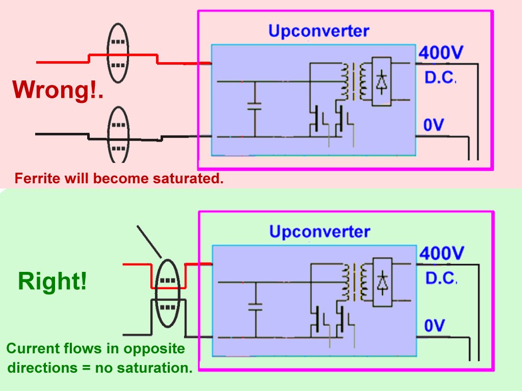
Fig. 5 - Correct and incorrect placement of ferrites on DC cables.
Because the inverter is the ‘culprit’ with regard to the interference signals (the panels themselves do not produce these interference signals), it is best to place the ferrite(s) as close to the inverter as possible. (The interference signals are transmitted to the DC cables by the current peaks within the inverter, whereby the cables can function as an antenna while the panels themselves have a very low impedance).
** If the installation works with a high DC input voltage, the wires must still go through the same ferrite (clamp) - there are questions and stories about the keep the two wires about 10cm apart, maybe for safety, but if the wires have the right insulation then there is no reason to use them at such a large separation. The ferrite must also have a reasonable 'coating', no sharp edges and of course enough space for the wires - but with a high voltage the current is much less than with (e.g.) 36V which means that the wires do not have to be so thick.
As for the wiring of the panels on the roof, it is also important that they are laid in the correct way. If there are a group of panels that need to be wired in series then there are basically 2 ways to achieve this. The first is to simply connect a wire from the inverter to the first panel and then to the next and so on to the last panel and then back to the inverter.
This is absolutely wrong - this wiring makes a very good antenna that can radiate the current peaks that the inverter requires as interference signals - the wiring is actually a nice ‘loop antenna’, and broadband too.
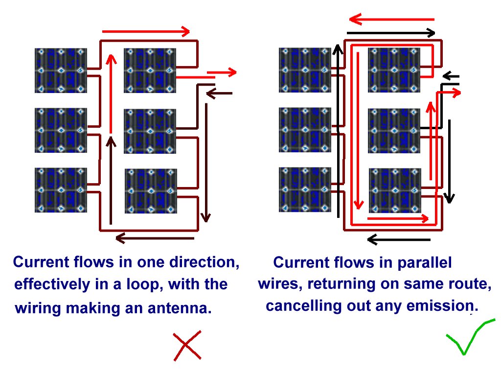
Fig. 6 - Wiring panels on the roof.
The second way of wiring is with the wires together, parallel, where a wire goes to the inverter to the first panel and from that panel to the next, and so on to the last - and then back along the same route, (if possible turned if possible), because then there is no loop because the current flows in the opposite direction along the return path.
(** Even with a high input voltage this can still be achieved by using wires with the correct insulation. In this way there is much less or even little radiation of interference signals.)
Some installers do not work this way because it costs more wire and more time, but these are actually false savings.
A.C. wires and ferrites...
On the inverter output wires (50Hz A.C., alternating current with no D.C. component) the current is much less than that which runs through the D.C. cables - for the same power that becomes about 7 times less current. However, it is also the case that each A.C. wire can have an interference signal on it.
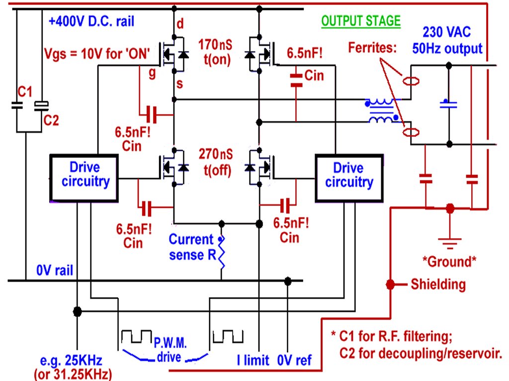
Fig. 7 - Output block of an inverter.
.
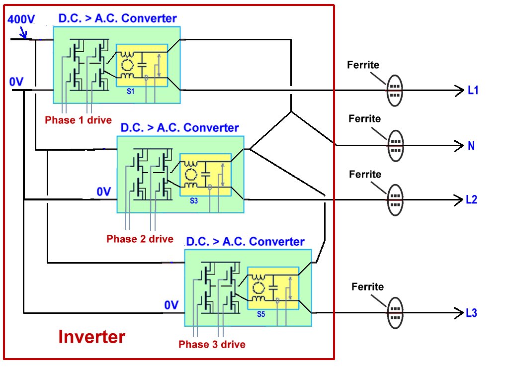
Fig. 8 - Placing ferrites on A.C. outputs.
This output is a balanced output in principle, so it is advisable to place a ferrite clamp on each wire - so on the live and also the neutral. If the installation is for a 3-phase output, then a ferrite is placed on each ‘live’ wire and a ferrite on the ‘neutral’ wire. Here it is also advisable to place the ferrites as close as possible to the converter.
Types of Ferrite....
There are different types of ferrite that can be used for our purposes but there are fewer differences between the types than many people think: what is important is that the ferrite works well against the frequency of the interference signals. A ferrite clamp on a cable could be seen in simple terms as a reactive inductance in series, so simply the higher the frequency the higher the impedance of the clamp. But a cable through a ferrite clamp not only contains this inductance but also e.g. capacitance with conductors close by, and also the self-capacitance of the construction - this means that each ferrite clamp and type of ferrite material has its own characteristics.
This means that the interference signal attenuation achieved by the placement of the ferrite clamp is frequency dependent but not necessarily in a linear way - there would be a certain area where a somewhat higher attenuation is seen and also an area where this attenuation would be lower than desired.
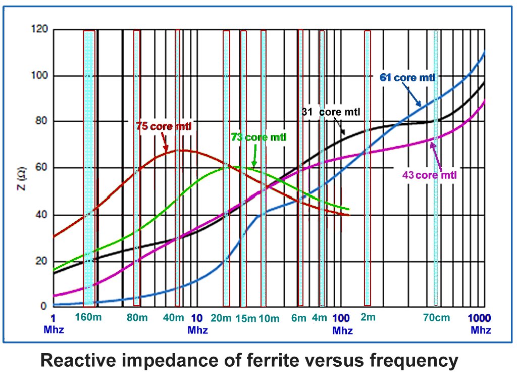
Fig. 9
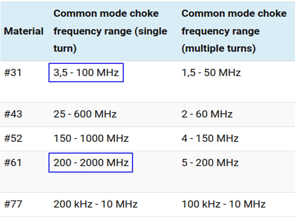
Figs. 9 and 10 - Types of ferrite.
What also affects the operation of a ferrite clamp are the temperature of the material, the ‘mix’ of different components in the material, and the size of the ferrite clamp. For those interested, the difference in inductance and frequency characteristics between a ferrite ring (closed) and a ferrite clamp (with a gap) of the same size are minimal when the clamp is closed - they do exist but are not of much relevance in this article.
Also of great importance is the ‘saturation’ of the ferrite - which depends on the current flowing through the ferrite. For example, we can take a ferrite of core composition ‘Type 31‘ or another, (this can be seen in various datasheets on the internet), as an example is the best solution in many installations and is used very often.
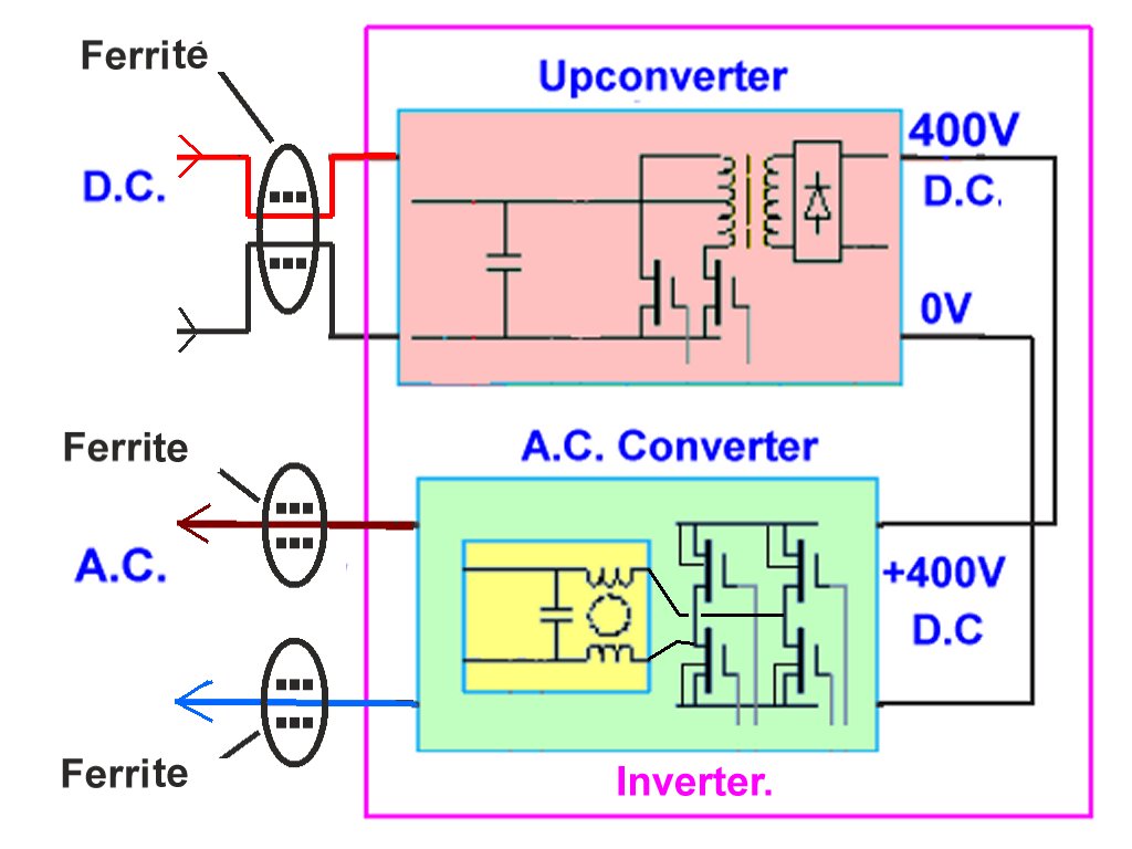
Fig. 11 - General placement of ferrite clamps.
Multiple ferrites...
If we notice that with 1 ferrite clamp there is an interference signal attenuated by -5dB compared to the original level, then we might think that extra (e.g. two or three) clamps offer a far better solution, perhaps around -15dB or -20dB. But nothing could be further from the truth - if we place a similar ferrite clamp extra on the cable, then that gives the same attenuation, but that attenuation is on an interference signal that is already -5dB from the original is (the attenuation is distributed over all ferrite clamps).
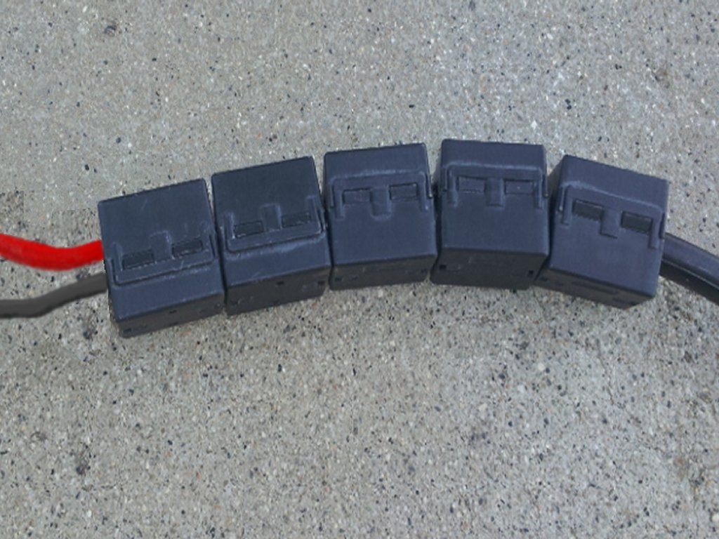
Fig. 12 - Placing multiple ferrites.
Let's look at a situation using resistors (instead of the reactive Xl resistance) in series to a certain output resistance.. Note - as an example I make a ‘load’ that takes the place of the load of all household electrical equipment that would exist in practice - and that load is not easy to determine because it would look different per minute or per hour, if TVs, washing machines etc. are switched on or off!
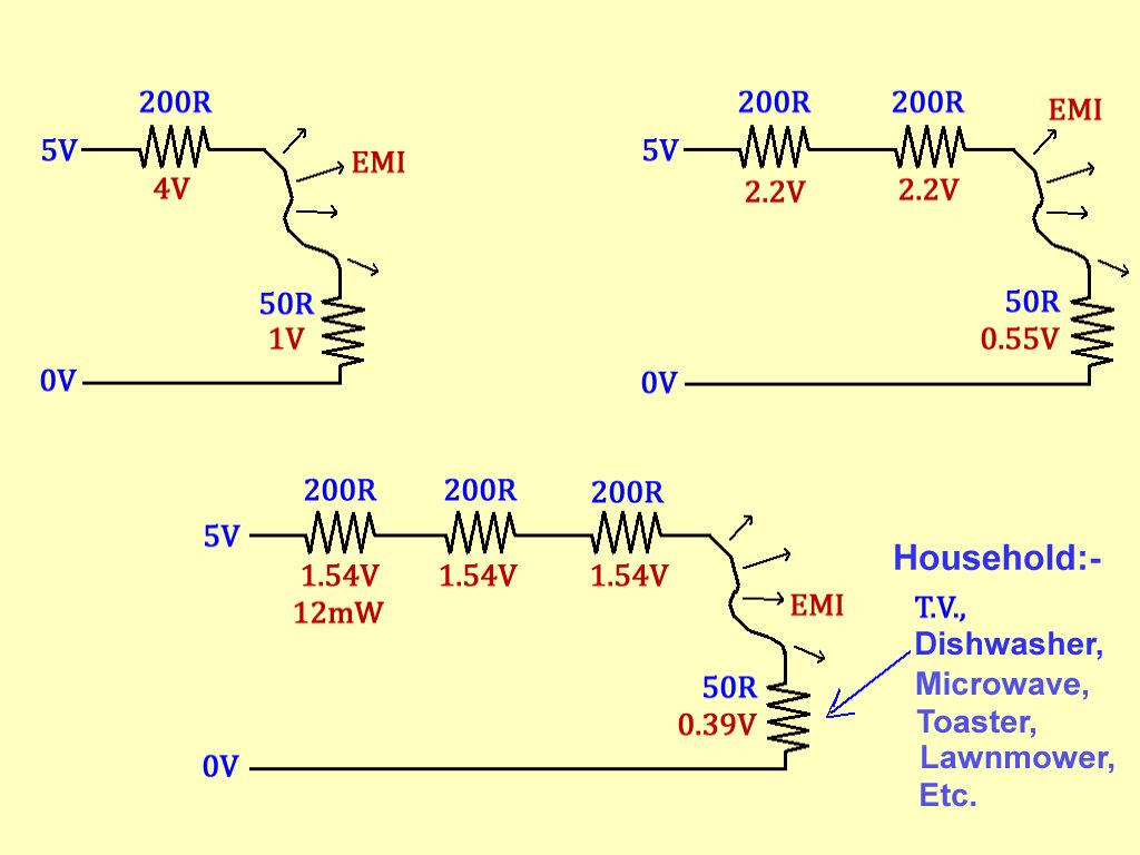
Fig. 13 - Extra 'ferrites' (resistors instead for an Xl example).
To start with we have a resistor (just like the effective resistance Xl of a ferrite) in series with a certain ‘load’ resistor. For an example let's put a 200-ohm resistor (instead of a ferrite Xl) in series with the ‘load’ of 50-ohms. With a (interference) signal input of 5 volts we would then have 4 volts over the series resistor of 200 ohms and 1 volt over the 50 ohms ‘load’. Now we think that it can be improved by putting a second ‘resistor’ in series. We would then have 400 ohms in series with the 50 ohm ‘load’. With that 5 volt interference signal we now have 2.22 volts over each 200 ohms and 0.56 volts over the 50 ohm ‘load’ - not 4V over each 200 ohms.
Let us then put another extra resistor in series, so 600 ohms in total in series. There would then be 0.39 volts across the 50-ohm ‘load’ - so with 3 ‘resistors’ in series instead of 1 we have about 40% of the voltage we have with only 1 series resistor - and that is less voltage drop across each series 200-ohm resistor (1.54 volts). So - with one ‘resistor’ we have 4 volts across each series resistor, with 2 resistors we have 2.22 volts across each series resistor, and with 3 resistors in series we only have 1.54 volts across each series resistor. In other words, by placing the extra ferrites in series, we do not get as much extra damping of the interference signals as we might expect.
Where extra ferrites can help is in situations where multiple frequencies need to be attenuated. Then a combination of a ferrite clamp of a certain type can be placed on the cable, followed by a second ferrite clamp of a different type that gives a high attenuation at a different frequency.
Another way to make the attenuation of interference signals higher per ferrite clamp is to make multiple windings of the wires through the ferrite, but because of the high current that is used, this is not easy to do because of the thickness of the wires, so that is why I discuss the one ‘winding’ mainly on the D.C. cable. but of both wires together. Also, multiple turns through a given ferrite will reduce the frequency at which it has peak attenuation.
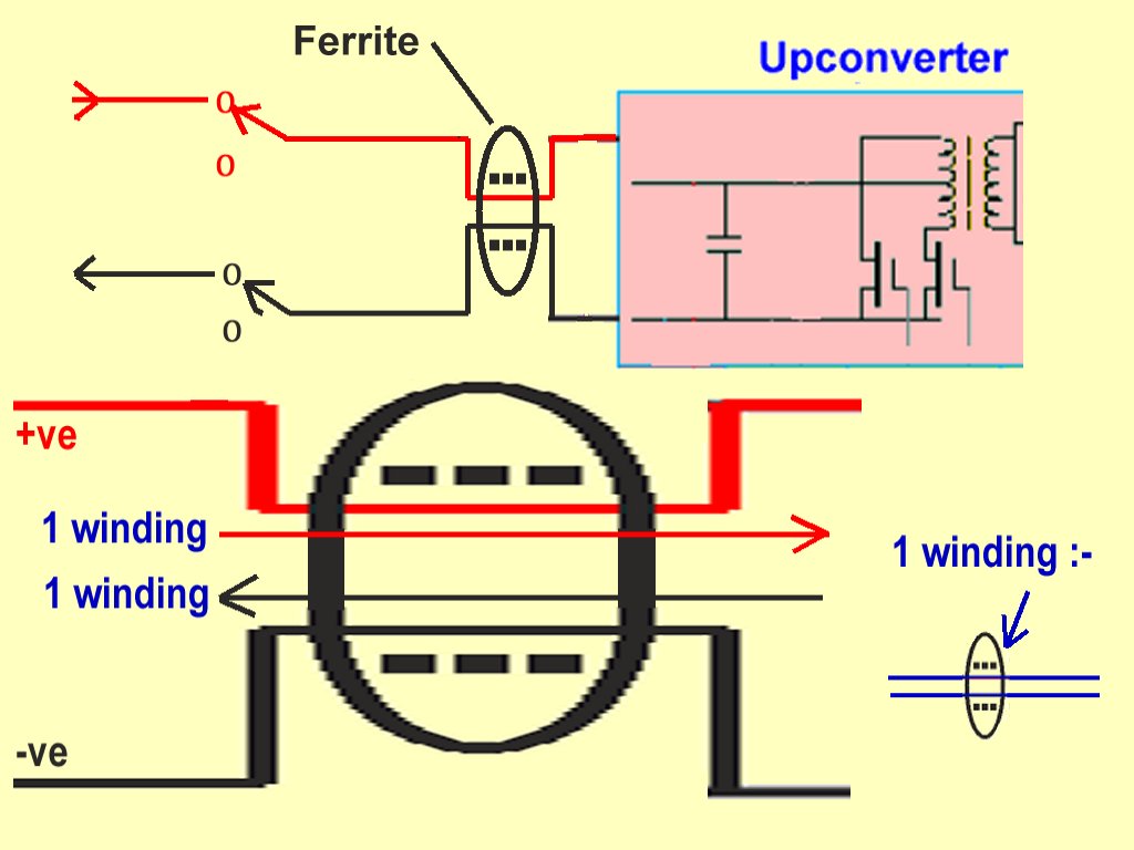
Fig. 14 - Only one 'winding' on ferrites.
Connection via Ethernet Cables:...
Many of the solar panel installations are implemented in such a way that the owner can view his savings, energy consumption, efficiency etc. via his computer, laptop or smartphone - which meant that the inverter must have a connection to the home network.
Sometimes this is achieved by an Ethernet cable that runs to an interface, e.g. a WiFi box or wired network switch. There are many different Ethernet cables (cables for between the router / modem at the front door and other network equipment that do not make connections via WiFi) and it seems that the knowledge about these cables, especially among electricians and installers, is not that prevalent.
Any ethernet cable used in the solar installation must also be prevented from causing interference - and this involves using the correct Ethernet interface cable as well as using an appropriate ferrite ring or clamp on the cable. To accomplish this, an understanding of the cable characterisitics should be gained together with knowledge of the frequencies involved. Note that the measures taken to avoid interference caused by the Ethernet interface are also beneficial to avoid other interfering signals from outside the installation from disrupting the operation of the installation itself.
First of all, the most common internet / Ethernet cable is a UTP which means Unshielded Twisted Pair where each pair can carry a data stream. Normally there are 4 such pairs in each cable, but not every pair needs to carry data - in some cables / systems there are fewer pairs in use. The pairs are twisted to give them a degree of protection and to give a balanced characteristic with the data sent in a differential mode.
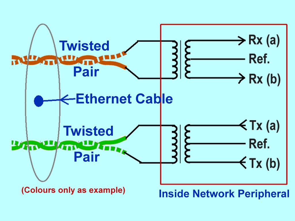
Fig. 15 - Ethernet data communication.
Types of Cables:..
There are 2 types of specifications that deal with aspects such as (a) the possibility of interference, and also aspects that deal with (b) the speed and/or bandwidth. I will not go into the co-ax cables that were also used in the past for networks. The 'Cat[x]' cables and variants thereof have performances that are generally better with the higher numbers (so: CAT6 is ‘better’ than CAT5, CAT7 is even ‘better’ than CAT6 but here there are also other differences). However, before a meaningful comparison can be made, the meaning of 'better' must be defined - i.e. what “better” actually means in the situation and/or system in which the cable is used - e.g. do you want to achieve the highest speed or bridge a very long distance or have the best protection.
There is also a CAT8, but we would rarely encounter this in a home or office - but in somewhat larger data centers such as Alphabet (Google) and so on. The UTP cables, 'STP', 'F/UTP', 'S/UTP' (etc.) cables have different types of protection and therefore better or worse as far as radio frequency interference is concerned.
There is no mystery concerning these cables, they even come from the old days as a development of the old telephone / data cables - CAT1 was a twisted-pair cable that was used for telephone (voice frequencies) and modem connections in the telephone network - and was analogue at the time. CAT3 was the first to have 4 twisted-pairs and provided digital voice signals and a 10Mbps data speed in general. This better performance, such as reduced crosstalk and the ability to work with higher data rates comes from different wire and insulation sizes and materials, and also the different construction of it such as the number of ‘twists per meter’, which has an influence on the signal quality, and the screening of the respective pair. Speaking of screening, there are 2 types:- braid and foil, but there are also 2 types of screening methods - all-around protection which is a layer of protection over the entire cable, and a type of screening which is around each pair. The latter gives much less crosstalk between the pairs which gives better performance.

Fig. 16 - Twisted pair 'twist rate'.
Data Transmission Speeds:..
. The specifications of these cables can also confuse people - sometimes the data rate is written (Mbps = megabits per second) and sometimes the bandwidth (in MHz) - and those figures are often very different! That is because of the way data is sent and how many pairs are used. Many of the specifications are given for cable lengths of 100m, but for some purposes such as patching between 2 switches etc., the cable is shorter and can carry a higher data rate.
Moreover, the data that runs over an Ethernet cable does not have to be a purely digital 1 or 0 with only 2 voltage levels (e.g. 2V and -2V) - the Ethernet standard knows e.g. ‘PAM’ which stands for “Pulse-Amplitude Modulation" where multiple voltage values have multiple meanings (more data bits). Just to give you an idea, one ‘bit’ (pulse) that is +2V could mean ‘11‘ in data, +1V would be ‘10‘, -1V would be ‘01‘ and -2V would be ‘00‘.... There are several types of PAM modulation systems but it is easy to see that with PAM, each pulse could mean multiple ‘bits’ - in the example above that is 4 values of data (= 2 bits) for one pulse.
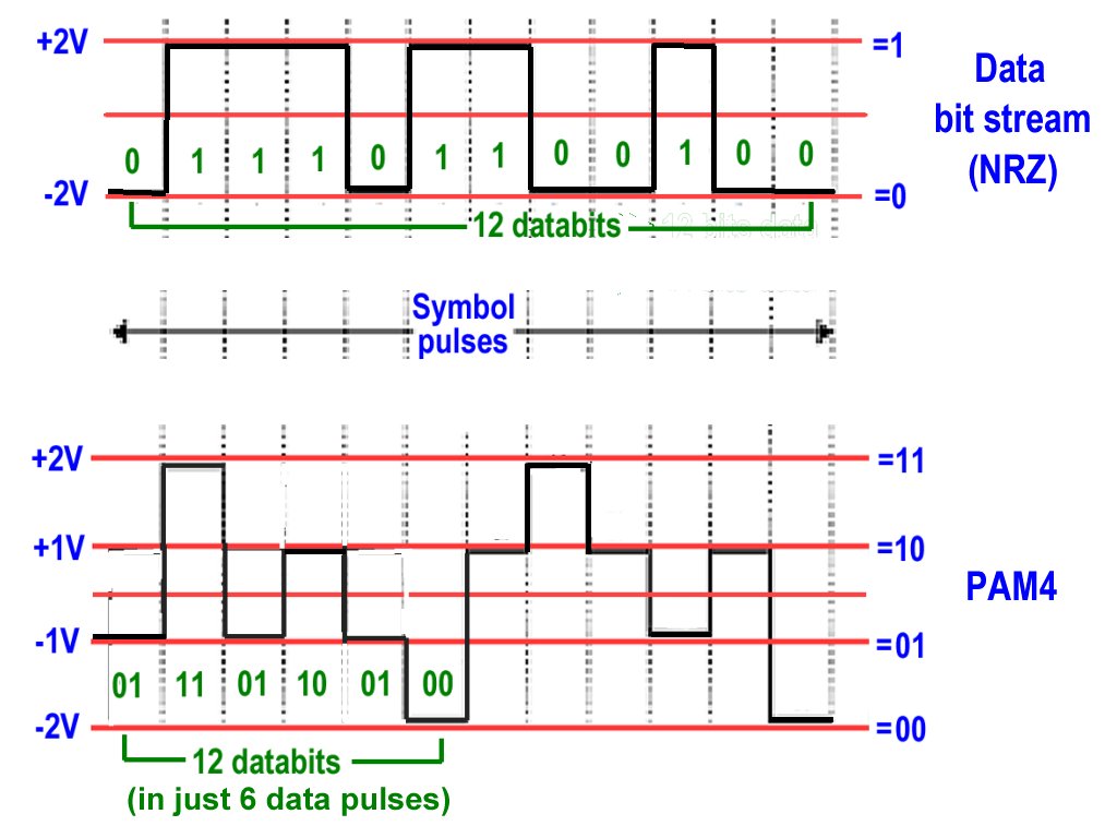
Fig. 17 - Pulse-Amplitude Modulation data.
Now, think of a fictional cable that has 10 twisted pairs of wires to it, each pair capable of carrying about 200MHz before noise or other interference is too high. That would have a ‘Bandwidth’ of 200MHz. But if 4 pairs out of 10 are in use, we can send 4 x 200 = 800 megapulses per second over the entire cable with the other pairs unused. Wait a minute - each pulse can have 4 meanings - 2 bits. We then have an effective data rate of 1600 Megabits per second (1.6 Gbps) while we have a cable that only has 200MHz bandwidth! (I haven't included other aspects here such as error-correction etc., but I think the principle is easy to understand).
Cable categories:...
So, with the type of construction and the signal shape used, for CAT5 the bandwidth is 100MHz, and there are only 2 pairs in use - 1 for ‘transmit’ and 1 for ‘receive’, which gives a data rate over 100m of 100Mbps.
For CAT5e (e stands for ‘enhanced’) has a better construction and also a bandwidth of 100MHz but gives a data rate of 1Gbps (1000Mbps) - the wires in the pairs are twisted tighter which gives a better signal quality.
CAT6 is a cable that has a bandwidth of 250MHz and also a data rate of 1Gbps but due to better shielding can carry about 10Gbps over a shorter distance of about 35 meters. It also has a plastic ‘seperator’ between the pairs which ensures good separation between each pair and therefore less crosstalk between them.
CAT6a has a bandwidth of 500MHz and can carry a data rate of 10Gbps over a length of 100m - again as a result of a better construction.
For CAT7 and higher I will not go into further because such cables are not really included in international standards and there are sometimes also differences in the connector types used.
Cable types:...
Next we can detail the types of cables - the different types and the name abbreviations have clear meanings. As already written above, UTP is actually the simplest cable with only the 4 pairs of wire, each twisted to form a twisted pair. There is no screening in this cable, only the pairs in a sheath. As a standard, the well-known RJ-45 connector is used on the ends of those cables - which is also used for the other cables below.
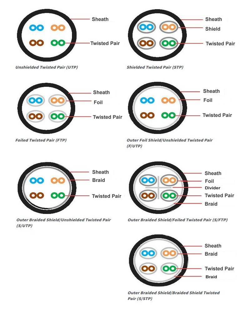
Fig. 18 - Types of Ethernet cable construction.
Type STP stands for Shielded Twisted Pair in which the shielding (screening) is placed around each pair which reduces the crosstalk between the pairs. The outside of the cable (under the sheath) has no other screening.
Type FTP stands for Foiled Twisted Pair and is almost the same as STP but with a metal foil around the pairs instead of braid. Just like with co-ax cable, braid can have gaps in it while a foil is a solid conductor.
Type F/UTP is a cable the same as UTP but with a foil protection under the sheath (so not a separate one over each pair).
Type S/UTP is like F/UTP but with a braid as protection material instead of a foil.
The S/FTP as you may have expected stands for Shielded Foiled Twisted Pair in which there is a foil protection around each pair and also a braided protection under the sheath. Sometimes there is also a plastic separator that creates a controlled, constant distance between the pairs, with less crosstalk as a result. There is also S/STP, which clearly means Sheilded STP in which there is a braid protection around each pair and also a braided protection under the sheath.
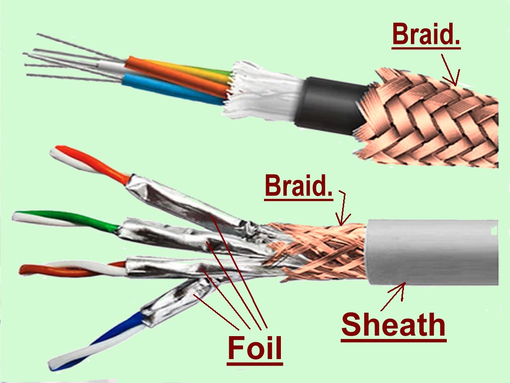
Fig. 19 - 'Braid' protection and Foil protection.
POE - Power Over Ethernet:...
Finally, some peripherals that are connected to a (home) network get their necessary power from the Ethernet cable itself - while there are no separate power lines in the cable (and also no ‘ground’ or ‘0V line’). This is only possible if the interface source has a POE supply implementation built in. We must remember that the data is sent over the wire pairs in a differential way, so the data has no relation to a ‘ground’ or a ‘zero volts’, the data is only determined by the voltage between the two wires in the pair. Also, one pair has no relation to another pair (at least it shouldn't - there can be crosstalk between the pairs which actually causes interference and therefore must be reduced as much as possible - hence the shield/screening around a pair as in STP etc.).
In order to let a supply voltage run over the Ethernet cable, 2 of the pairs are chosen - where the center of the data transformer or control electronics is connected to the +ve or the -ve of the DC power supply that is built into the interface box. This is therefore the ‘power supply side’ of the system, and supplies approximately 40V DC (in our case this could be the inverter's network interface for example). In the peripheral, (e.g. a WiFi interface but also in other situations something like a desktop telephone) there is also a transformer or electronics for these pairs and again the center points of these are connected, normally by a voltage regulator, to make a power supply for the peripheral.
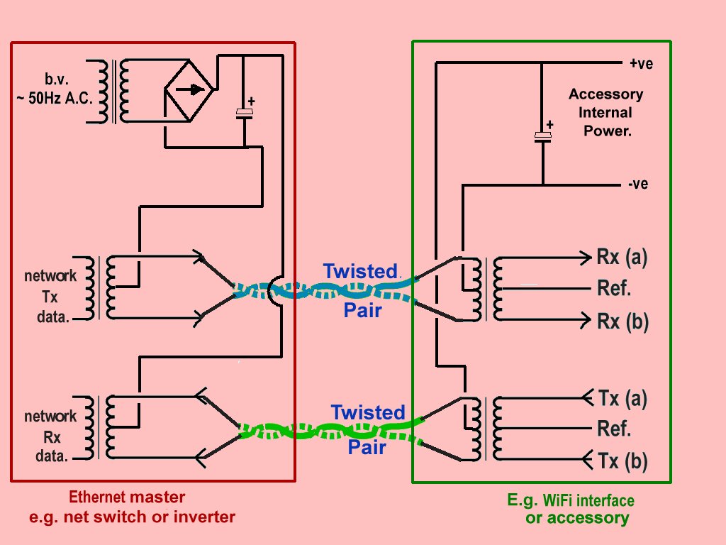
Fig. 20 - 'Power Over Ethernet' operation.
Conclusions:...
First of all, after several conversations and questions and also a lot of reading, I can see that if no improvement in the quality of the average solar panel installation is realised in the future, then ultimately far too many interference signals will become a regular part of the radio spectrum around us, and that will have a very negative impact on several essential services which will be at the expense of our society - in the form of poorer communication with e.g. ambulance and fire services, danger to shipping and aviation, (in aviation this is not only the comms between air traffic control and the pilot, but also items such as VOR beacons, and other instrumentation) and delays in the transport sector.
In order to reduce such interference that is caused by solar panel installations, a more effective regulation must be implemented with more enforcement. Nobody likes extra 'red tape' or excessive regulation, but certain rules and regulations serve to ensure compatibility between systems and the co-existence of services which use common resources. That is why there are regulations covering (e.g.) the use of our roads and the rules which apply to drivers.
However, in order to realize the proper regulation and control of solar panel energy systems, the installation companies must purchase the appropriate components and equipment, have the suitably relevant technical knowledge in-house, and have the necessary qualified personnel available for all installation work.
Some installation companies and suppliers of inverters do offer products which are well-screened and create little or no radio-frequency interference, as noted earlier these include inverters from Growatt and SMA.
Even if this can all be realised, they must also work in the correct manner, not only working to ensure the efficient operation of the installation but also to ensure proper grounding and screening and also to prevent possible interference signals.
This is not only in the interest of other users of the radio spectrum but also of the solar panel installation owners themselves:- it must not be forgotten that if there is incomplete attenuation of interference signals generated by the installation, it is in the other direction equally possible that signals from outside the installation could have an interference effect on the functioning of the installation. Especially in this time of ‘hacking’ and other radio spectrum problems (particularly as more and more of these installations become more densely spaced) this is an important aspect.
Furthermore, every installation must really be ‘complete’ before it is delivered - thus also verified in all relevant aspects. If the owner still has to do a lot of extra work after purchasing but before everything is in good order, it is a fine demonstration of a disgusting way to do business.
When I buy a new car, I do not expect that I still have to buy a battery, pump air into the tyres and check that the work brakes properly. I also do not need to know how the brake system is put together or how hydraulic systems work in general - that is what the garage, with its qualified technicians, is there for. That (average) garage only buys in its new cars if they have everything arranged as it should be, and also installs the right parts that are needed for the national market.
With the situation as it is now, I think we should 'wake up' the installation companies and also make sure that they gain insight and more knowledge by reading the papers and articles (such as this one but also those from the government and other authorities). That would not really be a complete solution but would still be a step in the right direction. Hence, if there is (still) a problem with interference signals then we can talk with the owner who (hopefully) shows some understanding, then we can come up with a possible solution with e.g. placing ferrites etc. - but we must also pay full attention because there could be some unexpected legal aspects which may arise, e.g. from the insurance company of the homeowner.
At a higher level, as individuals we have far less impact upon policy-making and the enacting of regulation than do various committees and institutions - what we can (and should) do is to use opportunities which arise to persuade authorities to investigate the effects of these installations and the measures they could use to prevent the associated R.F. problems from arising. It is in this way that meaningful and "fit for purpose" norms and standards can be established together with useful verification procedures defined - an acceptance test (a kind of "M.O.T. test") for new installations.
 You can E-mail theauthor of these pages (Trevor Gale) by using
this link, or by sending mail to tgale@tgale.net - criticism is welcome but constructive mails only, please!
You can E-mail theauthor of these pages (Trevor Gale) by using
this link, or by sending mail to tgale@tgale.net - criticism is welcome but constructive mails only, please!
